SPIDR Project : Visual Mapping with Distributed Swarms
This personal project focused on the development of my original quadruped design to a distributed swarm capable of collaboratively mapping an environment using onboard vision and range sensing. Each robot operates autonomously using a dual-microcontroller architecture: low-level servo and IMU control is handled by an Adafruit ItsyBitsy, while high-level perception, planning, and communication are managed by an ESP32 equipped with a camera and a TOF (Time-of-Flight) distance sensor. The robots communicate over a lightweight mesh network and contribute to a shared map through ROS 2-based modules. I designed and printed a custom PCB to integrate all components into a compact, power-efficient footprint.
Project Aim
The overall goal is to build a robust and scalable framework for real-time distributed exploration, with applications in search and rescue, environmental monitoring, and collaborative robotics research..
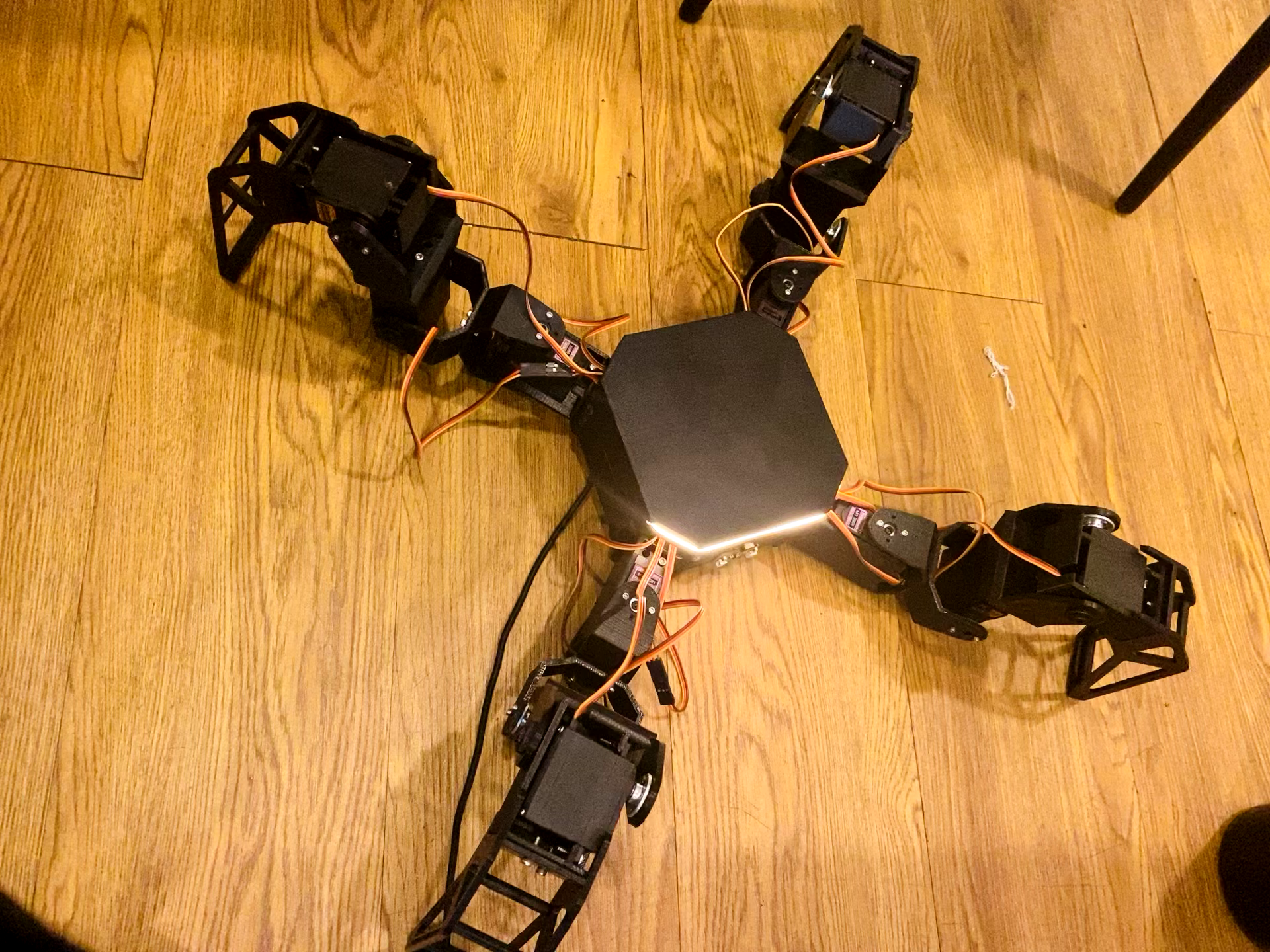
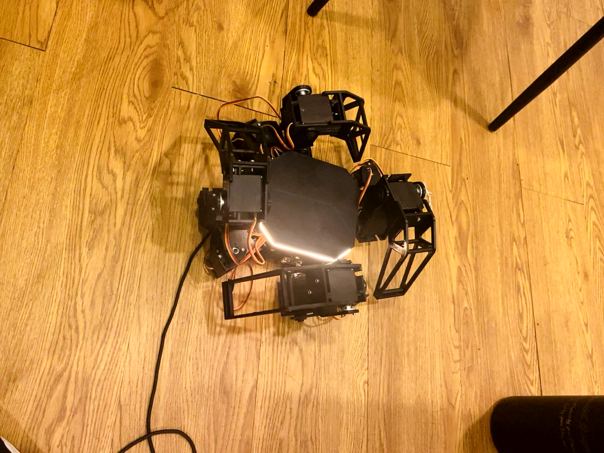
Single Unit in Deployed Exploration
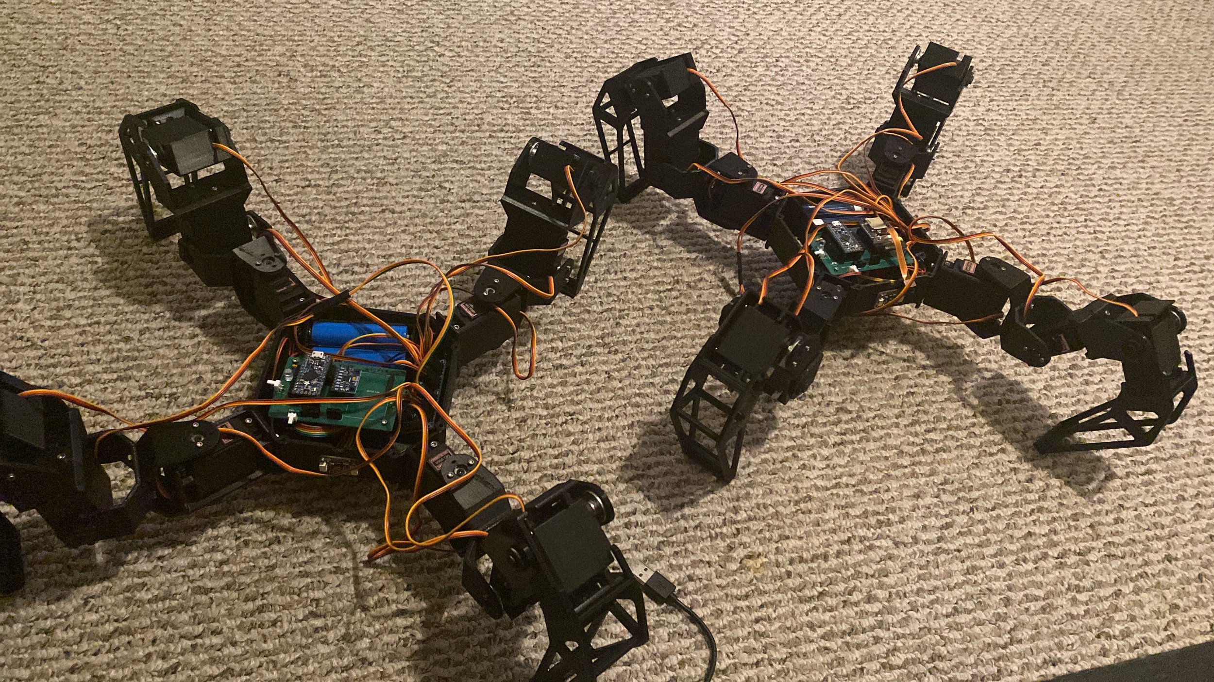
Swarm Obstacle Avoidance Testing during Development
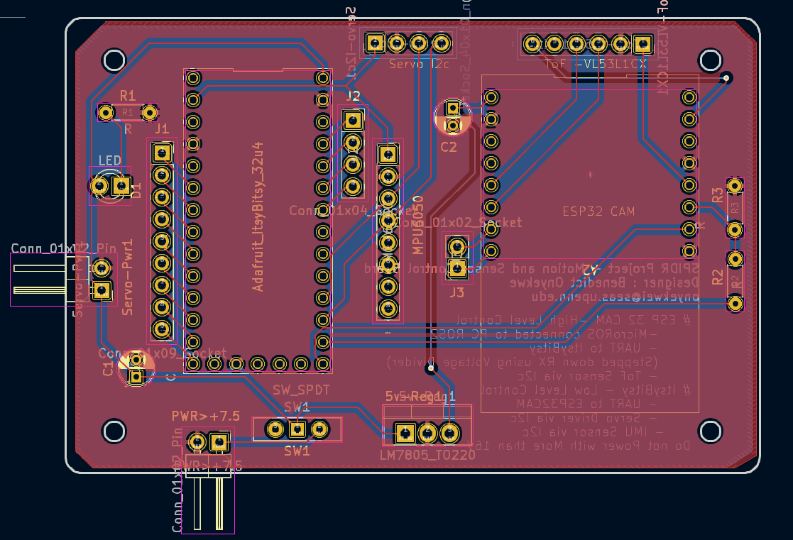
Designed PCB for Control and Sensor/Actuation Integration
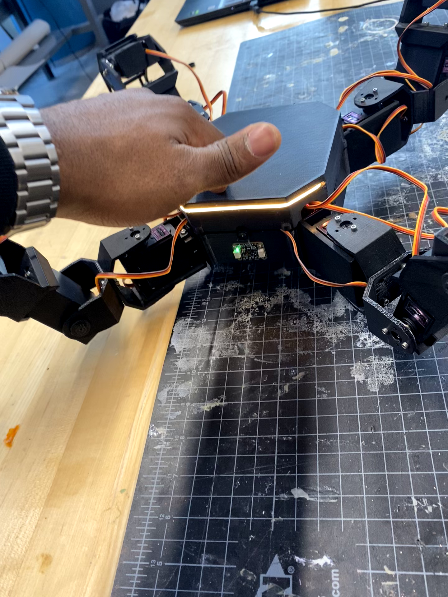
Single Unit Obstacle Avoidance
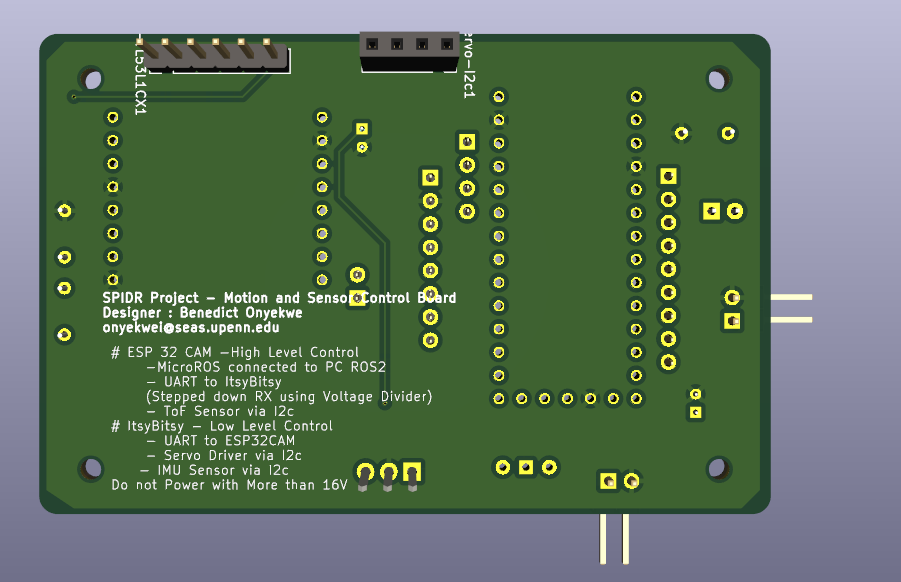
PCB Details
Project Work Breakdown
System Architecture
Hardware Architecture
Microcontroller Stack:
ItsyBitsy 32u4 for low-level control of servo motors and IMU integration and processing.
ESP32 for high-level processing including vision (camera) and Obstacle detection using TOF distance sensor.
Sensors:
IMU (MPU9250)for orientation estimation.
TOF Laser Distance Sensor for obstacle avoidance and elevation sensing.
Camera (OV2640 or similar) for visual SLAM and object recognition.
Custom PCB:
Designed and fabricated to consolidate power regulation, microcontroller interfaces, and motor/sensor wiring into a compact, robust board.
Actuation:
12 DOF using servo motors with PWM control via ItsyBitsy.
PID loops implemented for stable joint positioning.
Software Stack
ROS 2 Integration:
ESP32 communicates with ROS 2 nodes over micro-ROS for publishing sensor data and receiving high-level commands.
Map data, robot poses, and commands are exchanged in a single ROS 2 environment.
Control Pipeline:
ItsyBitsy: Handles motor PWM control, IMU filtering (Madgwick), and publishes configuration states to ESP32 via UART.
ESP32: Handles camera streaming, TOF-based range data processing, and swarm-level navigation decisions.
Visual SLAM and Mapping:
Camera data is used for lightweight visual odometry (on ESP32) or optionally streamed to an external ROS 2 server for RTAB-Map.
Each robot constructs a partial occupancy grid or point cloud that is shared with other units..
Key Features
Modular Distributed Swarm: Each robot operates independently and contributes to a unified map through swarm collaboration logic.
Dual MCU Architecture: Efficient split between low-latency control and computationally intensive planning/vision tasks.
Real-Time Mapping: Visual and range-based mapping allows for dense environment understanding.
Custom PCB Design: Simplifies integration, reduces wiring complexity, and enables easy scaling to more robots.
Implementation Challenges
Microcontroller ROS 2 Bridging using micro-ROS with memory-limited MCUs and this limits the functionalities that i can implement within the space and computational capacity of the microcontrollers .
Sensor Fusion across two microcontrollers with separate clocks and data pipelines.
Real-Time Networking between robots with limited bandwidth was challenging using Wi-Fi .
Loop Closure for Distributed Mapping: Without GPS, each robot operates in its own local coordinate frame with no absolute reference to the global environment. This makes it difficult to align maps across robots accurately, especially when they start in different locations or don't overlap early.